Raspberry Pi 3 Basics
Introduction
This post is a reference document for raspberry pi 3, it’s installation and basic functionalities. As a working example I’ll be using an LED circuit and try to turn it on and off using python API.

Things I used:
- Raspberry Pi 3 Model B
- GPIO extension
- Breadboard
- Wires
- Red LED
- Resistor 220 ohm
- 32 GB micro SD card
Installation
Raspberry pi has an official OS, Raspbian which I have installed on my microsd card using the official utility : RaspberryPi Imager Utility
The utility has an option to specify the wifi name and password and enable SSH with password. Once the installation is done plug in the card and power up.
You can access the machine using ssh
ssh [email protected]Getting to Know
Once you have the shell access you can run a few commands to better know the model and pin layout.
Model Info
cat /proc/device-tree/model
Raspberry Pi 3 Model B Rev 1.2
Pin Mapping
# pinout

,--------------------------------.
| oooooooooooooooooooo J8     +====
| 1ooooooooooooooooooo        | USB
|                             +====
|      Pi Model 3B  V1.2         |
|      +----+                 +====
| |D|  |SoC |                 | USB
| |S|  |    |                 +====
| |I|  +----+                    |
|                   |C|     +======
|                   |S|     |   Net
| pwr        |HDMI| |I||A|  +======
`-| |--------|    |----|V|-------'

Revision           : a02082
SoC                : BCM2837
RAM                : 1GB
Storage            : MicroSD
USB ports          : 4 (of which 0 USB3)
Ethernet ports     : 1 (100Mbps max. speed)
Wi-fi              : True
Bluetooth          : True
Camera ports (CSI) : 1
Display ports (DSI): 1

J8:
   3V3  (1) (2)  5V
 GPIO2  (3) (4)  5V
 GPIO3  (5) (6)  GND
 GPIO4  (7) (8)  GPIO14
   GND  (9) (10) GPIO15
GPIO17 (11) (12) GPIO18
GPIO27 (13) (14) GND
GPIO22 (15) (16) GPIO23
   3V3 (17) (18) GPIO24
GPIO10 (19) (20) GND
 GPIO9 (21) (22) GPIO25
GPIO11 (23) (24) GPIO8
   GND (25) (26) GPIO7
 GPIO0 (27) (28) GPIO1
 GPIO5 (29) (30) GND
 GPIO6 (31) (32) GPIO12
GPIO13 (33) (34) GND
GPIO19 (35) (36) GPIO16
GPIO26 (37) (38) GPIO20
   GND (39) (40) GPIO21
LED Circuit
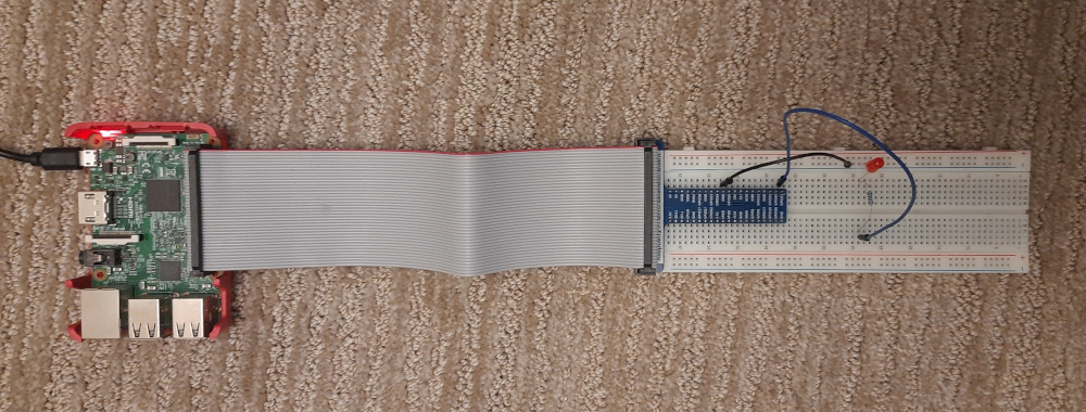
Raspberry pi provides a bunch of GPIO pins which can be controlled via the python API. Here I’m using a very basic LED circuit. The power source in this case will be the raspberry pi itself and the switch will be a logical one controlled by the python API.
Once the circuit is laid out as per the diagram and the image, test it by connecting the positive wire to the 3.3v pin (the first one). The LED should light up. Next connect the wire to any one of the GPIO labeled pins and head back to the shell.
Run the python shell using sudo
sudo python>>> import RPi.GPIO as GPIO
>>> GPIO.setmode(GPIO.BCM)
>>> GPIO.setup(21, GPIO.OUT)
>>> GPIO.output(21, True)
>>> GPIO.output(21, False)With these commands you should be able to control the LED switch. 21 comes from the pin 40 labeled GPIO21

